Testing and Confirming Wire Configuration of PV (DC) Disconnects
Mastering PV Disconnect Continuity Testing: MC4-Style and Conduit-Style
Introduction
When you’re installing your own solar system, one of the most important steps is making sure your PV disconnect is wired correctly and that the positive and negative (polarity) connections are lined up the right way. This simple check gives you the confidence that your disconnect will work as it should — safely shutting off your panels when needed and keeping your system running smoothly.
By verifying correct wiring, polarity, and terminal connections, you can prevent costly issues such as reverse polarity, miswiring, or faulty equipment. In this guide, we’ll cover both MC4-style and conduit-style disconnects, explaining how each works, how to test them step by step, and what to do if something doesn’t check out. Whether you’re maintaining a residential rooftop system or a larger commercial array, these procedures will help keep your solar installations safe, reliable, and efficient.
Understanding PV Disconnects
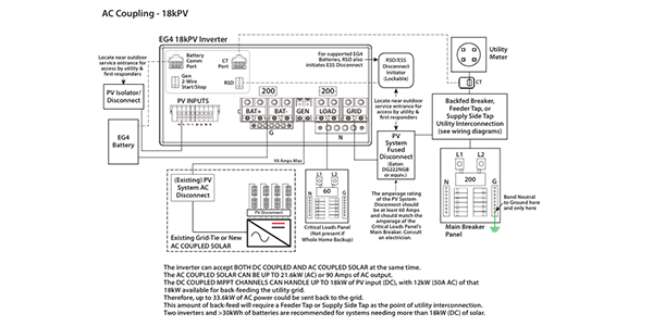
PV disconnects, also known as solar disconnects or DC disconnects, are essential safety devices in any solar installation. They serve as the primary means of disconnecting the solar array from the rest of the electrical system, allowing for safe maintenance, troubleshooting, and emergency shutdowns.
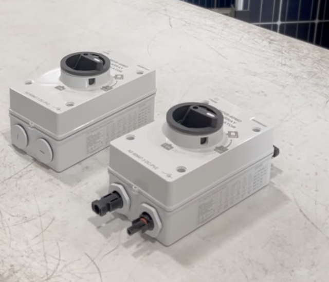
There are two main varieties of PV disconnects:
-
MC4-Style Disconnects – compact, plug-and-play units often used in smaller or space-constrained installations.
-
Conduit-Style Disconnects – more robust, panel-mounted disconnects used in larger or conduit-based systems.
Both types must be tested to confirm continuity and polarity before commissioning the system.
Checking Continuity on MC4-Style Disconnects
MC4-style disconnects are simple, compact, and widely used. Here’s how to test them:
Step 1: Set Your Multimeter
Switch your multimeter to the continuity test setting.
Step 2: Switch to “On”
Place the disconnect in the “On” position.
Step 3: Check Continuity
Test between the input and output terminals. You should hear a tone (or see a reading) for the correct pair, and silence for the opposite side.
Step 4: Confirm Polarity
Ensure the positive input aligns with the positive output, and the negative input with the negative output. Misalignment here causes reverse polarity issues.
Step 5: Switch to “Off” and Retest
In the “Off” position, there should be no continuity between input and output, confirming the disconnect isolates the circuit.
Checking Continuity on Conduit-Style Disconnects
Conduit-style disconnects are more complex, requiring extra steps:
1. Open the Disconnect
Remove the cover to expose terminals. Typically, the top is labeled 1, 3, 5, 7, and the bottom 2, 4, 6, 8.
2. Inspect Terminals and Wiring Diagram
Reference the included wiring diagram to confirm proper terminal pairings (e.g., 1→2, 3→4, 5→6, 7→8).
3. Test in the “Off” Position
No continuity should be present between proper terminal pairs. Continuity here indicates a problem.
4. Test in the “On” Position
Continuity should now exist between the paired terminals (1-2, 3-4, etc.).
5. Verify Mismatched Pairs
Cross-pairs (like 1-3 or 2-4) should never show continuity, regardless of switch position.
Common Issues and Troubleshooting
When testing either disconnect type, you may encounter:
-
Wiring Alignment Issues – If terminals don’t match correctly, you may detect reverse polarity or no continuity at all. Always confirm polarity before finalizing connections.
-
Lack of Continuity – If no continuity exists in the “On” position, inspect for loose wires, broken terminals, or internal component failure.
-
Reverse Polarity – Swapping positive and negative leads can damage equipment. Double-check every connection with your multimeter.
If you can’t resolve the issue through inspection, consult the manufacturer or replace the disconnect.
Maintaining PV Disconnect Reliability
Testing PV disconnects should not be a one-time commissioning step — it’s an ongoing part of maintenance. Regular checks help prevent hazards, downtime, and system inefficiency. A properly functioning disconnect protects both the equipment and the people working on it.
Conclusion
Making sure your PV disconnect is wired correctly and polarity is preserved is a vital step for every DIY solar installer. The process may differ slightly between MC4-style and conduit-style disconnects, but the goal is always the same: confirm that your system is safe, properly connected, and ready to perform.
By taking the time to double-check your wiring and polarity, you can catch errors early, prevent reverse polarity hazards, and protect your equipment. Doing this right isn’t just a box to check — it’s the foundation of a reliable solar setup that will run smoothly, stand the test of time, and give you confidence in your clean energy investment.
Watch Our Two-Part Video Series
|
|
|